did you know there is a plasict material that melts at about 60°C ? the official name / main ingredient is Polycaprolacton (PCL) (wikipedia: deen) product names i found:
the challeng is to get a good water bath in the right temperature. so for this i reused my HotPlate SMD soldering hardware. created a profile that just heats to 60°C and waits…
i will add some pictures and experiment results here in some days 😉
this morning i did a last test-run with the tweaked Felder ISO-Cream profile:
yeah… at the top i thought it is in the cooling step already and opened the window – with ~3°C cold air from outside it dropped fast.. then i found it is in the middle of the reflow – sorry… and closed the window again – until it really switched to cooling..
the old left-over pcb i use for these is done now.. i comes from my LEDBoard_4x4_16bit project – and if i remember correctly i backed it with the assembled board in the oven multiple times back then.. now grilled it again ~4-7 times. it smells very bad – is super dark discolored.. i think that is ok with about ~12 times solder cycles..
and then started to assemble a simple board to really test the profile 🙂
placed
then reflowed:
i added a paper-lid to have stable air inside..
reflow was successful 🙂 my profile is just a little bit to long for my right angle touch switches:
they melted away 🙁 – lesson learned – have a look in the datasheet and you know that they are very heat sensitive!
in general i have the feeling that my heating elements get a little bit to hot – the pcb also slightly discolored at on place… so will keep an eye on this and improve it..
Open Points
add housing
i would like to have class at the top for a good view what is happening inside..
first i just checked with low temperatures of 20..40°C as i went on and tested up to 260°C i noticed that the current did decrease. and the temperature did not increase any more. i could see this in my graph as the heating got slower and slower with the rising temperature… (also the pid already saturated at the output..)
so i measured the resistance during the cool down of the heating elements to get some insights: (4x in series → 48V/4=~12V/Module)
Temperature (°C)
Resistance (Ohm)
Current (A)
Power @48V (W)
255
40
1,19
57
250
39
1,21
58
240
38
1,23
59
230
36
1,26
60,5
220
38
1,26
60,3
200
34
1,35
64,8
100
26
1,8
88,6
80
24
2
96
60
22
2,18
104
40
20,9
2,3
110
25
19,5
2,46
118
Temperature / Resistance – 4 Modules in Series – 12V/Module
result: the ~57W is not enough to get to more than 255°C…
i rearranged the Modules into 3-in-series connection. this means ~16V/Module – and tested again:
Temperature (°C)
Resistance (Ohm)
Current (A)
Power @48V (W)
255
27,5
1,45
70
250
27,0
1,5
72
240
26,6
1,6
77
230
25,6
1,67
80
220
25,3
1,7
82
200
24,1
1,8
86
100
18,8
2,1
100
80
17,5
2,7
130
60
16,7
40
15,6
25
14,3
Temperature / Resistance 3 Modules in Series – 16V/Module
with this i found that i can go above 255°C.
i then tested the profile for the Felder ISO-Cream “Clear” and found that in the reflow stage the heat-up is a little to slow:
in the *my setup* picture is a temporary cardboard thing with a 80mm 12V fan (connected to 5V) to cool down faster between tests. for the final setup i think i will buy 1 or two 5V and PWM capable fans…. and also exchange the *chamotte* ston with some metal frame. this way i also can cool the bottom side..
so i again switch the configuration – now i have a 2-in-series config: 24V/Module CURRENTLY THIS TABLE IS ONLY CALCULATED VALUES!!
Temperature (°C)
Resistance (Ohm)
Current (A)
Power @48V (W)
255
20
2,4
115
250
19,5
2,46
118
240
19
2,52
121
230
18
2,67
128
220
17,5
2,74
132
200
17
2,82
135
100
13
3,69
177
80
12
4
192
60
11
4,36
209
40
10,45
4,59
220
25
9,75
4,92
236
CURRENTLY ONLY CALCULATED VALUES!!!! Temperature / Resistance – 2 Modules in Series – 24V/Module
i also tested this with the Felder profile:
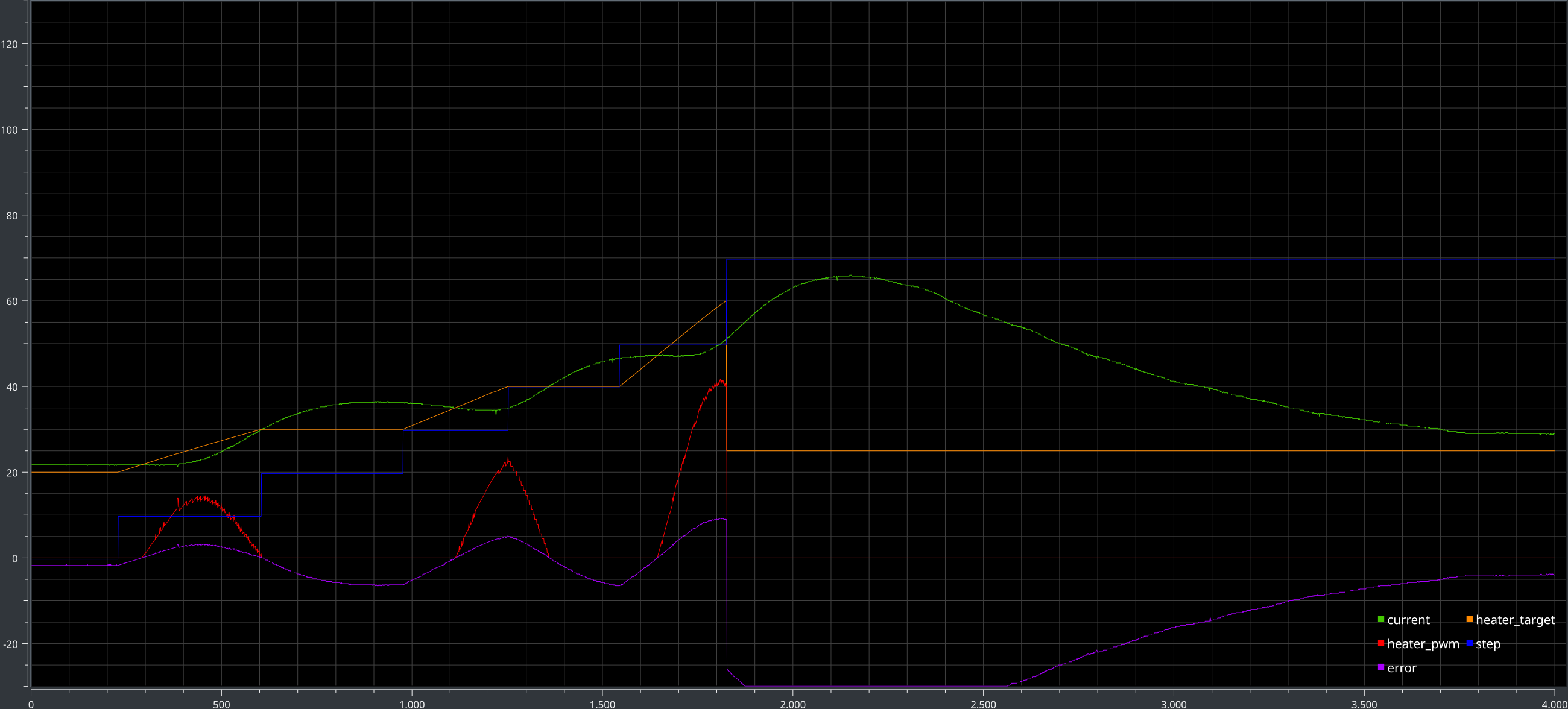
this time the heat-up is fast enough! 🙂 the nice and working pid tuning i had for the 4-in-series arrangement is now out of tune… so i will have to re-tune it to get less overshoot / swing.
while having a break i thought about the maximal power in this configuration – and found that this way i only be able to power 2×2 modules with my 250W power supply. for now i leave it this way. in the long run i hope with the other frame concept i get more heat to the pcb and less into the stone and this way be able to use the 3S config.
Tuning
after a day of mostly waiting til the system cooled down again – one test cycle <=60°C needs 400s → 6:40min – i just rebuild my hw mounting setup.
new setup
details of mounting
this way i can warm up quicker and cool down much quicker as i do not store heat in the stone. – at least that is what i hope..
plot with old setup
plot with new setup
hmmm – does not seem to change much..
i then tested the actual Felder Profile:
Felder ISO-Cream ‘Clear’ – Sn96,5Ag3,0Cu0,5 – 2S1P – P 04.50 I 00.00 D 00.00
seems i have a working profile. i will add a little more time for the prepare phase. so the pcb is really fully at the 50°C. at the top i have a little bit of a mis-match – i saw on my temp sensor directly connected to the heating elements at the top ~265°C – so that is hot… the pcb seems to increase its temperature resistance at higher temperatures… at the peak i have 230°C to 245°C error. and to the heating this results in ~35°C difference…
i will report when i solder the first real board. 😉
so when all the parts arrive i can go on.. with building.
for the Controller i plan to write it in CircuitPython and run it on an adafruit (maybe ItsyBitsyM4) PyBadge – for now i just want to use the arduino serial plotter or similar with an second CDC-device enabled to log the progress and the flash-drive function of CircuitPython for a text-file with the temperature-profile. i have written a request in the adafruit CircuitPython forum if there are any PID controller things out there…